Introduction
As photovoltaic (PV) systems demand higher accuracy and faster response in current measurement, traditional Hall-effect sensors reveal limitations in temperature drift, sensitivity, and linearity. Closed-loop fluxgate current sensors, renowned for their exceptional zero-flux control and superior accuracy, are becoming the preferred choice for real-time monitoring and protection in PV applications.
1. Operating Principle
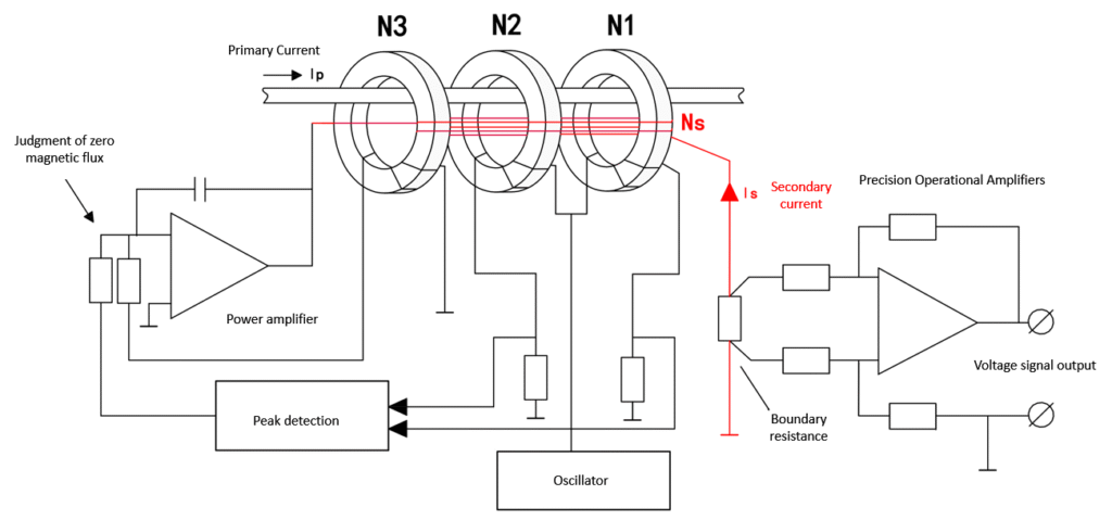
Closed-loop fluxgate sensors operate based on fluxgate effect combined with zero-flux feedback control. The core components include: High-permeability magnetic core, Excitation winding, Detection winding, Compensation (feedback) winding. The excitation winding applies an alternating magnetic field, periodically driving the core into saturation. In the absence of primary current, induced voltages in the detection winding cancel out symmetrically. When a primary current flows, it generates magnetic flux in the core, causing an imbalance in detection winding voltage. This error signal is processed by a control circuit that drives the compensation winding, producing an opposing flux to nullify the core flux. The compensation current is a highly accurate image of the primary current and can be converted to a voltage output using a sampling resistor.
2. Key Advantages
a) Superior Linearity and Accuracy: The zero-flux operating point eliminates core saturation effects, achieving linearity far beyond open-loop Hall sensors. Accuracy can reach the ppm level. b) Minimal Temperature Drift and Long-Term Stability: Because the core operates near zero flux, the temperature influence is negligible. c) Wide Bandwidth Response: Closed-loop designs maintain zero flux across low frequencies and DC, while at high frequencies the compensation winding behaves like a current transformer. d) Galvanic Isolation and Noise Immunity: The sensor provides electrical isolation between primary and secondary circuits, improving safety and reducing susceptibility to common-mode interference.
3. Structure and Functional Workflow
1. Excitation: The drive coil applies an alternating magnetic field, periodically saturating the core. 2. Error Detection: Any flux from the primary current induces an imbalance detected by the sensing coil. 3. Feedback Compensation: The control circuit amplifies the error signal and drives the compensation winding to cancel the flux. 4. Signal Output: The compensation current is measured via a resistor and converted to an output voltage or digital signal.
4. Applications in PV Systems
Leakage Current Detection, Inverter Current Monitoring, Residual Current Protection, Smart PV Solutions.
Conclusion
Closed-loop fluxgate current sensors combine high accuracy, low drift, wide bandwidth, and strong isolation, making them an ideal choice for PV systems. As the industry moves toward intelligent energy management and grid stability, this technology will play a critical role in enhancing system safety and efficiency.