1. Core Technical Principle: Hall Effect and Magnetic Concentration Design
The open-loop Hall current sensor is based on the Hall Effect discovered in 1879. When current passes through a conductor in a vertical magnetic field, a Hall voltage proportional to the current and magnetic field strength is generated at both ends of the conductor. Its core design adopts an “open-loop architecture”, which does not require a feedback coil to offset the magnetic field. Current measurement is realized through three key modules:
- Magnetic Core Module: Made of permalloy or ferrite materials with high magnetic permeability, it concentrates the magnetic field generated by the measured current into the sensing area of the Hall element, improving magnetic field density and measurement sensitivity;
- Hall Element: As the core of magnetic field-voltage conversion, it converts the magnetic field signal transmitted by the magnetic core into a weak Hall voltage (usually at the mV level);
- Signal Conditioning Circuit: Through amplification, filtering, temperature compensation and other processing, the weak Hall voltage is converted into a standard output signal (such as 0-5V, 4-20mA) to adapt to the backend control system.
When the measured current Iₚ flows through the primary wire, a magnetic field B is generated in the magnetic core. The Hall element senses B and outputs the Hall voltage V_H. The relationship satisfies the formula: V_H = K_H × Iₚ × B (K_H is the sensitivity coefficient of the Hall element). Since the open-loop design has no magnetic field offset link, V_H directly reflects the magnitude of Iₚ after conditioning, realizing real-time current measurement.
2. Technical Advantages: Why Choose Open-Loop Architecture?
Compared with closed-loop Hall current sensors, the open-loop architecture has unique advantages in photovoltaic, industrial control and other scenarios:
- Fast Response Speed: Without the charging and discharging process of the feedback coil, the response time can be as low as 1μs, which can accurately capture the instantaneous fluctuation of current in the photovoltaic system;
- Cost and Size Advantages: Eliminating the feedback coil and complex drive circuit, the volume is reduced by more than 30%, and the cost is reduced by 20%-40%, adapting to the compact layout of photovoltaic inverters;
- Wide Measurement Range: Through optimized magnetic core design, it can realize current measurement from several amperes to thousands of amperes, covering the full scenarios of distributed photovoltaics (small current) and centralized photovoltaics (large current).
3. Adaptability to Photovoltaic Scenarios: Solving Industry Measurement Pain Points
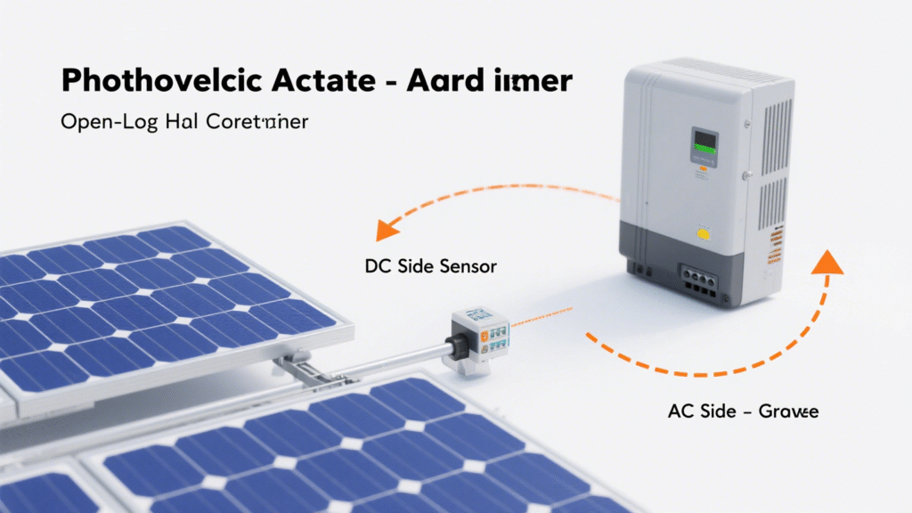
In photovoltaic systems, open-loop Hall current sensors are mainly used for current monitoring of inverters and combiner boxes, targeting three major pain points:
- Wide-Temperature Stability: Through the temperature compensation circuit, the measurement accuracy error can be controlled within ±1% in the photovoltaic outdoor environment of -40℃~85℃;
- Anti-Interference Ability: The magnetic shielding design is adopted to resist the electromagnetic interference (EMI) generated by the high-frequency switching of the inverter in the photovoltaic system, ensuring stable signals;
- Low Power Consumption: The static power consumption is only 1/5 of that of the closed-loop sensor, which meets the core demand of “energy saving and efficiency improvement” in photovoltaic systems.
4. Application Precautions
- Installation Spacing: The primary wire must pass through the magnetic core aperture in the center to avoid uneven magnetic field distribution caused by eccentricity, which affects measurement accuracy;
- Overload Protection: Choose products with overcurrent protection function to prevent the sensor from being damaged by large current when the photovoltaic system fails;
- Calibration Cycle: It is recommended to perform accuracy calibration every 1-2 years to ensure measurement reliability during long-term operation.